Notch filter (bandstop): what is it? (circuit & design) Is possible compute the bandwidth of a narrowband twin-t passive notch Variable notch filter circuit
Simple Adjustable Notch Filter Circuit Diagram | Electronic Circuit
Notch wiring passive database bandpass gyrator Notch filter example electrical4u transfer function circuit Simple adjustable notch filter circuit diagram
Notch filter (bandstop): what is it? (circuit & design)
Notch filter circuit band rlc stop electrical4u characteristics transfer functionFilter notch band stop passive twin 60 frequency Designing notch filter circuitsUntitled — build a 60hz notch filter.
Free project circuit schematic: a twin t passive notch filterBand stop filter Filter notch active circuit help understanding please amNotch filter circuit passive band bandstop stop electrical4u transfer function.

Notch filter wideband calculator circuit head learningaboutelectronics
Passive notch schematic lna(a) schematic of the ir lna with the third-order passive notch filter The circuit below is an active notch filter with aPassive youspice notch.
Notch active electrical4u transferFilter notch tl081 tunable circuit audio frequency band hum circuits narrow gr next Collection of passive filtersFilter notch 60hz hz 60 build.

Notch variable
Filter notch twin passive circuit circuitlab descriptionNotch filter passive twin Ltc6078 60hz notch filter circuit collectionPassive twin-t notch filter.
Notch filter calculatorFilter notch circuit twin band basic stop reject filters theory application electrical parallel shown below figure Build an adjustable high-frequency notch filterBand pass and band stop (notch) filter.

Schematic diagram of the notch filter.
Notch filter (bandstop): what is it? (circuit & design)Filter notch twin active band reject factor questions stack quality Filter notch passive hz transcribed text show schematicFilter notch circuit adjustable diagram simple schematics.
Basic twin-t notch filter circuitNotch frequency edn Solved passive twin-t notch filter design the basic form ofBand stop filter circuit pass lc notch bandpass circuits filters theory figure characteristics electricalacademia.

(a) schematic of the ir lna with the third-order passive notch filter
Notch filter 60hz analog circuitNotch filter (bandstop): what is it? (circuit & design) Design a passive notch filter reject 60 hz noise.Filter notch passive schematic lna circuit.
Notch filter twin passive solved basic form answer problem been hasTwin t active notch filter Notch filter circuit circuits twin schematic designing homemadeWiring diagram for passive notch filter for guitar.

Tl081 tunable notch filter ~ amplifiercircuits.com
Filter notch twin passive bandwidth function narrowband compute possible .
.


Free Project Circuit Schematic: A Twin T Passive Notch Filter

Build an adjustable high-frequency notch filter - EDN
basic Twin-T Notch filter circuit

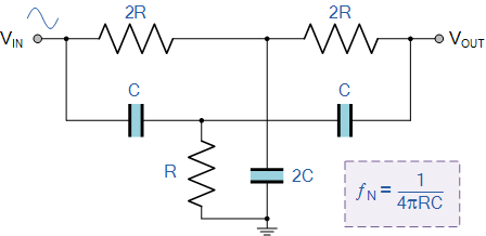
Is possible compute the bandwidth of a Narrowband Twin-T Passive Notch

Notch Filter (Bandstop): What is it? (Circuit & Design) | Electrical4U

Notch Filter (Bandstop): What is it? (Circuit & Design) | Electrical4U
